Within computer vision applications, capturing data is an important step that requires the right hardware, which itself has specific requirements.
Hardware must process data efficiently in either parallel or serialized threads. It must also be low cost, fast processing, and portable, and must have optimized memory architecture for more immediate memory access.
In this article, we'll cover five leading types of hardware that are driving computer vision applications, including:
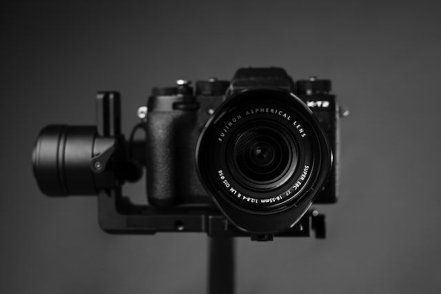
1. Cameras
Computer vision applications are typically divided into the following categories: position inspections, quality/count inspections, dimension inspections, and defect/foreign matter inspections. It’s important to choose the right camera for each application.
Cameras are usually grouped into:
- High-resolution types
- Compact types
- High-speed types
- Standard types
Different types of cameras
Line scan cameras
Builds up an image one line at a time by using a line sensor that passes in a linear motion over a specific object. An object can also pass in a linear motion under a sensor.
- Infrared
- CMOS
- GigE
- CCD
- CoaXPress
- CameraLink
3D cameras
These imaging devices allow for depth perception in images, replicating three dimensions as seen through human binocular vision.
- 3D laser profile sensors
- 3D line profile cameras
- 3D time of flight
- 3D fringe projection
- 3D stereo cameras
Area scan cameras
A rectangular-shaped sensor captures a single image in one frame, which results in an image with a width and height directly corresponding to the number of pixels on a sensor.
- CCD
- CameraLink
- HDMI
- GigE
- CoaXPress
- Infrared
- FireWire
- Board level
- HD-SDI
- CMOS
- USB
High-speed recording cameras
Specialized cameras offering high-speed image capture while maintaining a high resolution. They capture over 1,000 frames per second at megapixel resolution.
Contact image sensors (CIS)
Image sensors utilized in flatbed scanners almost in direct contact with the objects being scanned. A possible alternative to line scan cameras.
Smart cameras
Stand-alone and self-contained vision systems with built-in image sensors. Both the image sensor and vision system can be integrated into a single piece of hardware, which is known as an intelligent image sensor or a smart image sensor.
2. Lighting
Lighting is perhaps the number one cause of delays and overrun costs in computer vision. It’s critical for the creation of a strong and timely vision inspection, and failure to adequately illuminate targets can result in loss of productivity and information. Common lighting sources are LED, xenon, fluorescent, metal halide (mercury), and quartz halogen.
Foundations of illumination in computer vision:
- Geometry. 3D spatial relationship among the light, sample, and camera.
- Pattern or structure. Shape of the projected light onto the sample.
- Color or wavelength. How light is differentially absorbed or reflected by samples and immediate background.
- Filters. Differentially passing and blocking wavelengths and/or light directions.
Illumination techniques
1. Backlighting
Projects even illumination from behind a target, which provides a highlight of the target’s silhouette. Used to detect the presence or absence of gaps or holes, identify bubbles, cracks, or scratches, and measure or verify the outline shape of the target in clear target parts.
2. Dark field lighting
Provides light at a shallow angle to the target, and any surface features like edges, scratches, or notches will reflect the light back to the camera. The features appear bright and the rest of the surface stays dark.
3. Bar lighting
Offers a strip of light on a target or alongside the target’s edge for uniform illumination over a localized area. Can be used in combination with other bar lights to help illuminate a target from all directions.
4. Dome lighting
Offers uniform lighting from several angles, which results in no glare – even in mirrored objects. It’s often called “cloudy day” illumination because it eliminates uneven lighting, like shadows and glare, and evenly spreads light over the surface of a part.

5. Diffuse on-axis lighting
Also known as co-axial lighting, it uses a mirror to send light rays at a 90° angle to the target. It highlights specular surfaces perpendicular to cameras, meaning that any surface at an angle to the camera will show up dark.
6. Diffuse dome/ring lighting
Scatters light to minimize glare on reflective surfaces and can be applied to all directional lighting like ring, bar, or dome, to offer a more uniform spread of light over the target.
7. Ring lighting
Circle or ring of intense lighting offering shadow-free illumination and high-quality contrast. This lighting is common due to its versatility, though it can cause specular glare on reflective areas.
8. Low-angle dark field lighting
Provides light at an exceptionally shallow angle between 10°-15° to the target. Surface features like scuffs, dust, and more on mirrored surfaces will reflect the light back to the camera, which makes them appear bright and the rest of the surface appear dark.
9. In-sight integrated lighting
This diffuse ring light offers bright uniform lighting on targets. It minimizes shadowing and offers uniform illumination on matte objects. Because of the diffuse nature of the light, it also provides dark field lighting techniques at close working distances below 70mm.
10. High-powered integrated lighting
Offers polarized or non-polarized lighting onto targets.
11. Polarizers
Polarizers are filters placed in front of the camera lens and LEDs at a 90° angle offset. These are used in imaging applications to minimize glare or hot spots and to enhance contrast for the recognition of entire objects.
12. Color filters
Create contrast to darken or lighten an object’s features. Opposite-color filters darken, like using red light to darken green features, and same-color filters lighten, such as using red light to make red features appear brighter.
What to take into account for optimal lighting solutions:
- Ambient light contribution
- Immediate inspection environment
- Sample/light interactions
- Sample composition and transmittance
- Color analysis
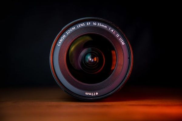
3. Optics
In computer vision, optics and optical elements like lenses, illuminators, prisms, and mirrors are designed and built to enable visual inspections in automated environments. Automated visual inspections often include:
- Correct orientation and position in space
- Presence or absence of defects
- Shape, size, and dimensional stability
- Color, appearance, and other optical properties
The lens is extremely important, as it captures information to be recreated by software, and it often operates under specific conditions for the best performance:
Diffraction and distortion
Diffraction, or lens blur, minimizes contrast at high spatial frequencies, which reduces the quality of an image. The difference between ideal and real lens behavior is called aberration.
Distortion is a specific type of aberration causing magnification differences in an image. Software can help to compensate for this issue.
Resolution
Resolution is related to the computer vision system’s ability to reproduce an object in detail. Smaller sensors can’t distinguish the finer details of objects, and even large and sophisticated sensors have to be used with a specific level of zoom and separation.
Field of view
The field of view is the area imaged by the lens, which should include all features the system has to inspect. When it comes to applications that include gauging and alignment, the field of view presents an image in a fixed geometry that’s calibrated to the position of the object.

Sensor size
Dictates the active area of the sensor and is usually measured in the horizontal dimension. The ratio between the field of view and the sensor size gives the lens’s primary magnification.
Depth of field
The maximum object depth the lens can hold in focus. Depth of field also calculates how much working distance variation is possible while making sure the lens maintains acceptable levels of focus.
Working distance
Refers to the distance between the lens and the object.
Contrast and filtering
Contrast refers to the separation in the intensity of white and black areas in an image. The higher the difference between them, the higher the contrast will be. A good lens can enhance the contrast even when the position, sensor, and focal length aren’t changed.
Color filtering is a way of increasing contrast. Basic lenses and sensors might be ideal for specific industrial applications but only show menial differences between colors. A filter of the appropriate color will increase contrast and compensate for any light variations in the environment.
4. Frame grabbers
This computer vision component captures individual, still frames from either a digital or an analog video stream. These frames are usually in digital form and are transmitted or displayed for analysis.
Frame grabbers tend to connect to PC systems through standard interfaces like Ethernet or USB. Newer frame grabbers can also capture several inputs at the same time, transform images, and perform real-time compression.
Frame grabber circuitry:
- Analog frame grabbers. The input signal conditioner buffers the analog video input signal to protect downstream circuitry. The video decoder converts SD analog video, such as PAL (Phase Alternating Line) or SECAM (Séquentiel de couleur à mémoire, which is French for color sequential with memory) to a digital format.
- Digital frame grabbers. A digital video decoder that interfaces to and converts a particular type of digital video source, like SDI (Serial Digital Interface), DVI (Digital Visual Interface), or LVDS (Low-voltage differential signaling).
- Analog and digital frame grabbers. Both types of frame grabbers have memory for storing acquired images, a bus interface so that a processor can control the acquisition and access to data, and a general-purpose I/O for triggering image acquisition or controlling external equipment.
5. Processors
A processor is a logic circuit that both responds to, and processes, basic instructions behind a computer. As it’s responsible for interpreting the majority of computer commands, it’s seen as the most important integrated circuitry in a computer.
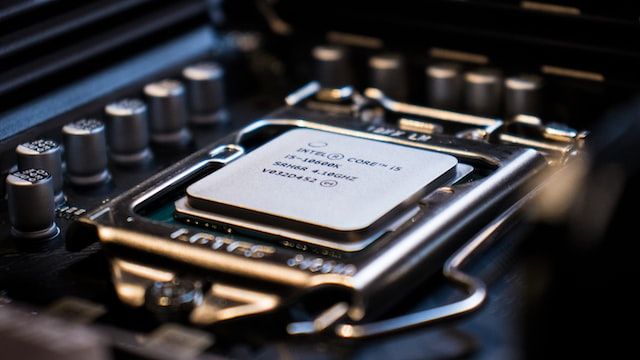
CPUs
Central Processing Units (CPUs) are in almost every device, from smartwatches to smartphones, and even thermostats. They process and execute instructions, acting as the brain of the device.
CPUs can only work alongside other hardware, with the chip sitting in a special socket within the main circuit board – the motherboard or mainboard. They’re separate from the memory, where data is stored temporarily, and from the graphics card, which renders video and 3D graphics.
They’re built by placing billions of microscopic transistors onto a single computer chip, allowing for the chip to make all the calculations needed to run programs. One of the most common evolutions in CPU technology includes making transistors smaller, resulting in the improvement of CPU speed – or Moore’s Law.
Some mobile devices have a System on Chip (SoC), which is a chip that packages CPU and other components, offering more than standard CPU functions.
GPUs
Graphics processing units, or GPUs, are also known as graphics cards or video cards. All computers need a GPU to render images, 2D or 3D animations, and video. It makes quick math calculations, freeing up the CPU for other activities. A GPU has thousands of smaller cores for multitasking.
There are two different types of GPUs:
- Integrated GPUs. Built into the processor, these don’t use a separate memory bank for graphics and video. These GPUs use system memory, shared with the CPU, using less power, creating less heat, and allowing for longer battery life. Commonly found on laptops and other smaller form factor systems.
- Discrete GPUs. Separate from the processor, these have their own dedicated memory not shared with the CPU. They consume more power and generate more heat, but offer higher performance. Commonly found in desktop PCs.
ASICs
Application-specific integrated circuits, or ASICs, are microchips designed for specific applications. ASICs might be contrasted with general integrated circuits like random access memory chips or microprocessors in computers. The two main design methods are:
- Gate-array design. Non-recurring engineering costs are lower, as no design work is needed. Production cycles are shorter thanks to metalization, which is relatively fast compared to full-custom design. In this manufacturing method, transistors, diffused layers, and other active devices are predefined. These ASICs are also larger and have a larger power requirement.
- Full-custom design. These ASICs are more complex, but they let chips do more. The size of the ASIC can often decrease in relation to a gate-array design because of the customization level and deletion of unneeded gates.
FPGAs
Field programmable gate arrays, or FPGAs, are semiconductor devices based around a configurable logic block (CLB) matrix, which is connected through programmable interconnects. FPGAs can be reprogrammed for specific functionalities or applications after manufacturing.
This separates ASICs from FPGAs, as the former are custom-made for specific tasks. However, one-time programmable (OTP) FPGAs are available. Today’s FPGAs have unprecedented logic density, as well as digital signal processing (DSP) blocks, embedded processors, and more.
Heterogeneous systems
Heterogeneous systems can contain several different computational units like CPUs, GPUs, FPGAs, digital signal processing units (DSPs), and AI accelerators. A big driving force behind the development of these systems is the next generation of adaptive, intelligent, and autonomous systems that form the base for autonomous manufacturing, vehicles, and more.
A big challenge is to make use of their huge computational power without compromising energy efficiency, dependability, performance, and time predictability.
Embedded system
These microprocessor-based systems have software designed for specific functions. These functions can perform either as an independent system or as part of a larger system. At its center is an integrated circuit for real-time computation operations.
Embedded systems are managed by digital signal processors (DSPs) or microcontrollers, GPU technology, FPGAs, and gate arrays. These are integrated alongside components dedicated to handling electric and/or mechanical interfacing.
Firmware, the embedded system’s programming instructions, is stored in flash memory chips or read-only memory, and run using limited computer hardware resources. The firmware also connects with the outside world via peripherals, linking output and input devices.
Basic structure of an embedded system:
- Sensor. Measures and converts physical quantity to an electrical signal. It stores the measured quantity in the memory.
- A-D converter. Analog-to-digital converter that converts a sensor’s analog signal sent into a digital signal.
- D-A converter. Digital-to-analog converter that changes the digital data from the processor to analog data.
- Actuator. Compares the A-D converter’s output to the actual output stores, then stores the approved output.
Microcontroller boards
Microcontroller development boards are printed circuit boards (PCBs) with hardware and circuitry designed with features to make experimentation easier. These boards are combined with memory, a processor, a chipset, and onboard peripherals with debugging features (keypad, LCD, serial port, and more).
Popular development boards include:
- Raspberry Pi
- BeagleBone
- AdaFruit Flora
- Arduino UNO


AI accelerator insider insider
Thank you for subscribing
Level up your ai accelerator insider career & network with ai accelerator insider experts.
An email has been successfully sent to confirm your subscription.
 Follow us on LinkedIn